

On January 13, 2026, BMIC LLC obtained U.S. Patent No. 12,525,912 titled “Solar Roof Panel System with Edge and Surface Treatments” (“the ’912 patent”). The patent discloses electric solar collectors for placement on the shingled roof of a structure such as a residential home. The ’912 patent, 1:22-24.
According to the ’912 patent, conventional solar modules may be considered “unsightly for use on roofs of residential homes,” and may obscure the “architectural contribution” of the shingles of a residential home. The ’912 patent, 1:39-43. The ’912 patent also states that conventional solar modules may require customization to accommodate the different size and shape of the roof plane upon which it is to be installed. Id. at 4:3-7. As a result, the outer perimeter of the bank of solar modules may include one or more irregular side edges that are not only unsightly, but also reduce the ability of the bank of solar modules to shed water, and instead accumulate materials such as “rain, snow, soot, dirt and plant materials such as leaves, twigs, and branches, which can result in stains and/or water damage to the roof.” Id. at 4:18-25. Figure 1 illustrates such irregular side edges:
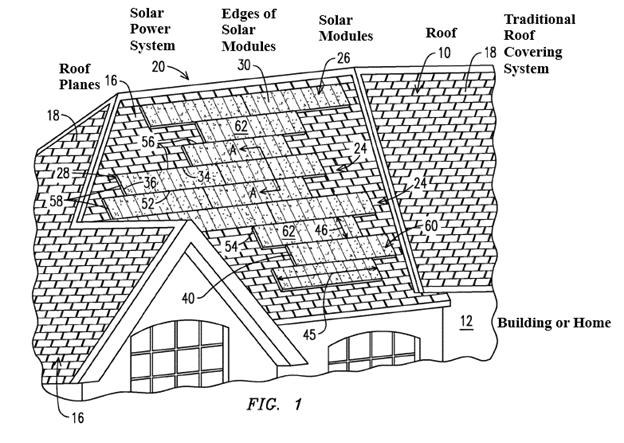
The ’912 patent, Fig. 1 (annotated).
The ’912 patent discloses a system that includes non-power generating “dummy panels” that are installed adjacent to these irregular edges. The ’912 patent, 1:62-64. These dummy panels mimic the appearance of the active solar modules but are specifically adapted to be cut in the field to form a continuous perimeter edge. Id. at 1:67-2:4. Figure 4 illustrates such dummy panels:
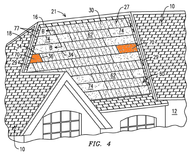
The ’912 patent, Fig. 4 (annotating dummy panels 70 in orange).
The ’912 patent discloses that the “substantially smooth and uniform top surface” of the bank of solar modules and dummy panels provides for “the effective shedding of rain, snow and ice, as well as a uniform and continuous outside perimeter edge. . . that reduces the likelihood that water, soot, dirt and plant materials may be captured and held without an outer boundary of the bank of panels.” The ’912 patent, 5:46-54.
The ’912 patent further discloses that the dummy panels can receive various surface treatments. According to the patent, these surface treatments can “produce the appearance of a plurality of smaller, standard-sized shingles or roofing tiles to break up or hide the true size of the panels, ” such as shown in Figure 7 below. The ’912 patent, 5:65-7:2. The patent also believes that these surface treatments may be used to increase “the efficiency or effective range of power generation of the solar modules by deflecting, diffusing or otherwise redirecting the sunlight over a broader portion of the photovoltaic cells.” Id. at 6:6-12.
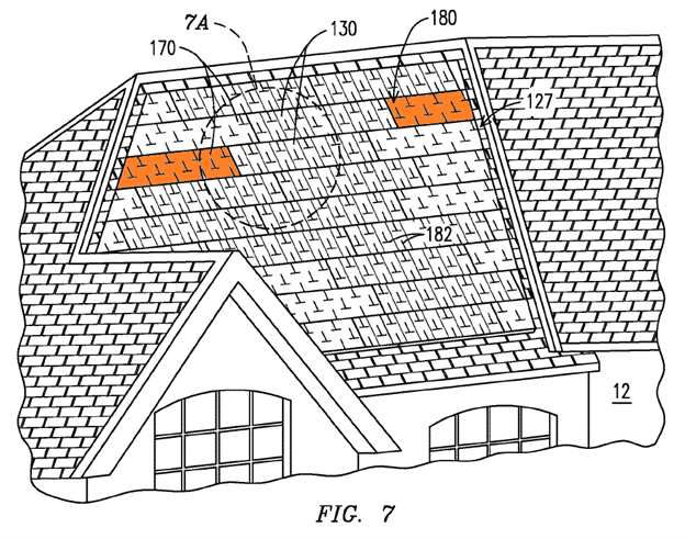
The ’912 patent, Fig. 7 (annotating the surface treatment 180 and dummy panels 170 in orange).
Claim 1 of the ’912 patent recites:
A solar power system, comprising:
a roof deck;
a plurality of solar modules installed above the roof deck,
wherein the plurality of solar modules comprises at least a first solar module and a second solar module,
wherein the first solar module and the second solar module are installed above the roof deck on a first roof plane, wherein the first roof plane is oriented in a first direction,
wherein each of the first solar module and the second solar module comprises:
a plurality of side edges, and a top surface extending between the side edges,
wherein the top surface of the first solar module comprises a first groove and a second groove,
wherein the first groove extends in a first direction,
wherein the second groove extends in a second direction,
wherein the first direction of the first groove and the second direction are different from one another, and
a plurality of non-power generating modules installed above the roof deck,
wherein the plurality of non-power generating modules comprises at least a first non-power generating module,
wherein the first non-power generating module is installed above the roof deck on a second roof plane, wherein the second roof plane is oriented in a second direction,
wherein the first roof plane is a different roof plane than the second roof plane, wherein the second direction of the second roof plane is different that the first direction of the first roof plane,
wherein the first roof plane and the second roof plane are non-coplanar and intersect at an edge,
wherein the first non-power generating module comprises:
a plurality of side edges, and a top surface extending between the side edges of the first non-power generating module,
wherein the top surface of the first non-power generating module comprises a third groove and a fourth groove,
wherein the third groove extends in a third direction,
wherein the fourth groove extends in a fourth direction, wherein the third direction and the fourth direction are different from one another.
The ’912 patent, 7:2-51.