

On February 5, 2026, the ITC found, in an initial determination, that violation occurred in its unfair imports investigation of Shoals Technologies Group, LLC’s complaint against Ningbo Voltage Smart Production Company and Voltage, LLC over U.S. Patent Number 12,015,375 (“the ’375 patent”) and family member U.S. Patent Number 12,015,376. Shoals Techs. Grp., LLC v. Ningbo Voltage Smart Prod. Co., Inv. No. 337-TA-1438, Initial Determination (U.S. Int’l Trade Comm’n Feb. 5, 2026). On February 24, 2026, following an evidentiary hearing, the ITC issued its Initial Determination on Violation of Section 337 and Recommended Determination on Remedy and Bond upholding validity and finding direct and indirect infringement of both patents. Id., Initial Determination on Violation of Section 337 and Recommended Determination on Remedy and Bond (U.S. Int’l Trade Comm’n Feb. 24, 2026).
The ’375 patent, titled “Lead Assembly for Connecting Solar Panels and Power Inverters,” discloses a lead assembly that includes drop lines joined to a feeder cable to bypass the need for a combiner box. The ’375 patent, Abstract.
According to the ’375 patent, in solar power installations, energy collected from multiple solar panels must be consolidated before it can be fed into an inverter. The ’375 patent, 1:46-49. Conventionally, the industry has relied heavily on centralized combiner boxes to handle this consolidation. Id. at 1:28-30. The patent identifies several significant shortcomings with this purported conventional approach, including combiner boxes being “clumsy, prone to damage and malfunctioning,” demanding regular maintenance and requiring extensive planning and skilled labor to install properly, and their relocation being a labor-intensive process that adds danger, manpower requirements, and expense. Id. at 1:50-57.
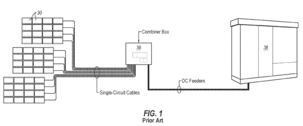
Figure 1 illustrates the prior art system including a conventional wiring configuration where each solar panel must be individually wired to a central combiner box. The ’375, 2:24-27.
The ’375 patent, Fig. 1.
The ’375 patent describes a lead assembly designed to render the combiner box unnecessary. The ’375 patent, Abstract. The assembly utilizes at least one drop line that is securely joined directly to a main feeder cable at a connection point referred to as a “nexus.” Id. at 1:65-2:1. The drop line connects to a solar array’s wire harness, while the main feeder cable routes the combined electrical power straight to the inverter, or to a trunk buss jumper. Id. at 2:2-4.
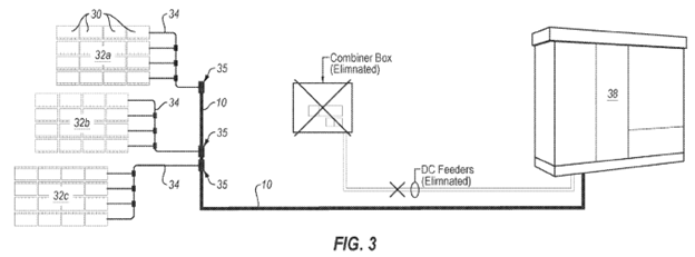
Figure 3 illustrates the system using a lead assembly. The ’375 patent, 2:31-32. Specifically, Figure 3 illustrates a plurality of wire harnesses coupled to the lead assembly, which then connects directly to the inverter, eliminating the combiner box completely. Id.
The ’375 patent, Fig. 3.
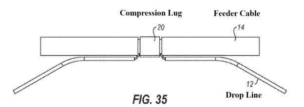
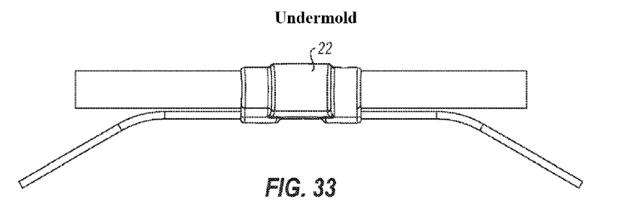
Figure 35 illustrates the drop line and feeder cable being held together by compression lug 20, which is surrounded by an undermold. The undermold, in turn, is surrounded by an overmold. The ’375 patent, 4:55-60. According to the patent, this structure “is profoundly durable, resistant to environmental factors such as temperature fluctuations, debris, and moisture, and is strong enough to be buried.” Id. at 6:7-10.
The ’375 patent, Fig. 35 (annotated).
The ’375 patent, Fig. 33 (annotated, illustrating the undermold).
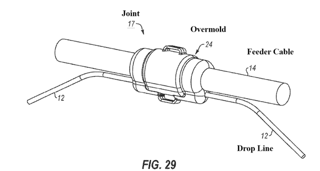
The ’375 patent, Fig. 29 (annotated, illustrating the overmold).
Figure 37 illustrates the internal construction of a joint, where the exposed wire of the drop line and the feeder cable electrically couple at the nexus. The ’375 patent, 3:16-17; 5:58-62.
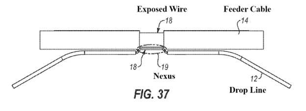
The ’375 patent, Fig. 37 (annotated).
Claim 1 of the ’375 patent recites:
A lead assembly for electrically coupling one or more drop lines to a feeder cable, the lead assembly comprising:
a joint where a section of the feeder cable and a section of the one or more drop lines can be electrically coupled at a nexus, the joint including the section of the feeder cable and the section of the one or more drop lines; and
a monolithic mold that encapsulates the nexus, the monolithic mold further comprising:
a feeder pathway extending completely through the monolithic mold and configured to allow the feeder cable to extend completely through the monolithic mold; and
one or more drop line pathways that each extend at least partially through the monolithic mold, and each configured to allow one of the one or more drop lines to extend at least partially through the monolithic mold;
wherein:
each of the one or more drop lines are configured to be capable of receiving electrical power from a plurality of solar panels for combination at the nexus to the feeder cable;
one of the one or more drop lines includes a section of exposed wire at the nexus;
the feeder cable includes a section of exposed wire at the nexus; and
at least a portion of the section of exposed wire of the drop line is parallel to at least a portion of the section of exposed wire of the feeder cable; wherein the one or more drop line pathways and the feeder pathway extend parallel to one another within the nexus, and the monolithic mold has distinct openings at ends of the feeder pathway and one or more drop line pathways through which the one or more drop lines and the feeder cable exit the monolithic mold.
The ’375 patent, 6:49-7:18.